
Page 187 - Power Electronics Handbook
P. 187
Bi-directional converters 179
chapter concludes with a description of gate-control and voltage-
multiplication circuits, which is a special application of rectification.
9.2 Bi-directional converters
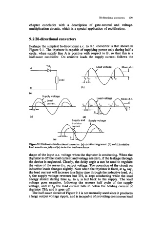
Perhaps the simplest bi-directional a.c. to d.c. converter is that shown in
Figure 9.1. The thyristor is capable of supplying power only during half a
cycle, when supply line A is positive with respect to B, so that this is a
half-wave controller. On resistive loads the supply current follows the
B fb)
Supply voltage
fd)
SUPP~V and SUPPIY voltage
Rlpre 9.1 Half-wave bidircctiond converter: (a) circuit arrangement: (b) and (c) resistive
load waveforms; (d) and (e) inductive load waveforms
shape of the input a.c. voltage when the thyristor is conducting. When the
thyristor is off the load current and voltage are zero, if the leakage through
the device is neglected. Clearly, the delay angle 01 can be used to regulate
the value of the mean d.c. output voltage. The operation of the circuit on
inductive loads changes slightly. Now when the thyristor is fired, at bl say,
the load current will increase in a finite time through the inductive load. At
tl the supply voltage reverses but TH1 is kept conducting while the load
energy stored during time bl to tl is fed back to the supply. The load
voltage goes negative, following the reverse half cycle of the supply
voltage, and at tl1 the load current falls to below the holding current of
thyristor THI and it goes off.
The half-wave circuit of Figure 9.1 is not normally used since it produces
a large output voltage ripple, and is incapable of providing continuous load