
Page 191 - Power Electronics Handbook
P. 191
Bi-directional converters I83
voltage rating, so that a bridge converter can prove cheaper, although
this is not necessarily so when the current ratings of the devices
increase. When considering costs it is also necessary to add the price
of control systems, and since a push-pull converter uses fewer
thyristors, and they have a common cathode, the cost of its drive
circuitry should be less than for a comparable bridge converter.
(iii) In a push-pull converter there is only one thyristor in any conduction
path between the supply and the load, whereas a bridge system has
two series thyristors. Therefore the efficiency of a bridge converter
would be expected to be lower than a comparable push-pull circuit
although, since the thyristors normally have a drop of the order of
one volt, this would only have a significant effect on very low voltage
supplies.
Single-phase circuits are relatively simple in construction, but they are
limited in power-handling capabilities and produce output voltage ripple
which is much greater than that from three-phase systems. The circuits
described so far can be termed two pulse, Le. the ratio of the fundamental
d.c. voltage ripple frequency to that of the input a.c. supply is two. The
greater the pulse number, the lower the smoothing requirements of the
circuit.
I Load 1
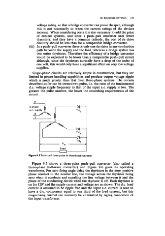
Blpre 9.5 Push-pull three-pulse bi-directional converter
Figure 9.5 shows a three-pulse push-pull converter (also called a
three-phase half-wave converter) and Figure 9.6 gives its operating
waveforms. For zero firing angle delay the thyristors in the most positive
phase conduct to the neutral line, the voltage across the thyristor being
zero when it conducts and equalling the line voltage between it and the
phase of the conducting device when the thyristor is off. Each thyristor is
on for 120" and the supply current and voltage are as shown. The d.c. load
current is assumed to be ripple free and the input a.c. current is seen to
have a d.c. component equal to one third of the load current, but this
magnetising current can normally be eliminated by zigzag connection of
the input transformer.