
Page 190 - Power Electronics Handbook
P. 190
182 Phase-controlled rectification and inversion
varying load power factor as the firing angle is changed. For net
rectification this power factor is lagging, although for inversion it
changes to leading.
(iii) The mean d.c. load voltage decreases as the firing angle (Y is
increased, and beyond 90" delay the voltage goes negative, reaching a
peak negative value at 180'. Clearly, for a.c. to d.c. rectifier systems
the negative voltage period is undesirable.
(iv) The value of the d.c. ripple voltage also increases as the firing angle is
increased, up to 90" delay. Beyond this point the ripple in the
negative voltage decreases as (Y is increased to 180'.
(v) The period for which a thyristor is reverse biased reduces
progressively as the delay angle increases to 180". A thyristor must, of
course, be reverse biased for greater than its turn-off time in order to
be successfully commutated. Therefore the maximum delay angle can
never be raised to 180" and for practical systems it is normally limited
to about 165" on SoHz systems. If a thyristor is not successfully
commutated it will commence conduction the instant its anode
voltage goes positive and so provide a complete half cycle of power to
the load. There will therefore be an abrupt change in the converter
operating mode from almost full inversion to full rectification.
Push-pull converter circuits are popularly used in applications which
require an input transformer either for isolation purposes or for effective
phase number increase. As will be seen later, the larger the number of
input phases, the lower the d.c. voltage ripple and the higher the power
which the converter can handle. However, when an input transformer is
not essential a bridge system is often more economical, a single-phase
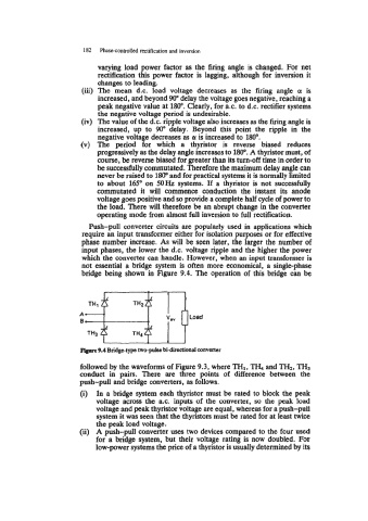
bridge being shown in Figure 9.4. The operation of this bridge can be
6
TH1
A-
0-
TH3 TH4
Figwe 9.4 Bridge-type two-pulse bi-directional converter
followed by the waveforms of Figure 9.3, where THI, TJ& and TH2, TH,
conduct in pairs. There are three points of difference between the
push-pull and bridge converters, as follows.
(i) In a bridge system each thyristor must be rated to block the peak
voltage across the a.c. inputs of the converter, so the peak load
voltage and peak thyristor voltage are equal, whereas for a push-pull
system it was seen that the thyristors must be rated for at least twice
the peak load voltage.
(ii) A push-pull converter uses two devices compared to the four used
for a bridge system, but their voltage rating is now doubled. For
low-power systems the price of a thyristor is usually determined by its