
Page 188 - Power Electronics Handbook
P. 188
180 Phase-controlled rectification and inversion
current. There are several ways in which it may be extended to full-wave
operation, generally these systems falling into two groups:
(i) Push-pull converters, which require a tapped transformer input.
(ii) Bridge converters, where an input transformer may be used but is not
an essential requirement for correct system operation.
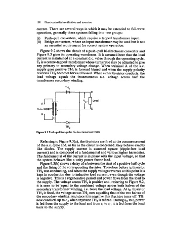
Figure 9.2 shows the circuit of a push-pull bi-directional converter and
Figure 9.3 gives its operating waveforms. It is assumed here that the load
current is maintained at a constant d.c. value through the operating cycle.
T1 is a centre-tapped transformer whose turns ratio may be adjusted to give
any primary to secondary voltage change. When terminal A of the a.c.
supply goes positive THl is forward biased and when the supply polarity
reverses TH2 becomes forward biased. When either thyristor conducts, the
load voltage equals the instantaneous a.c. voltage across half the
transformer secondary winding.
A.C. supply 3
Figure 9.2 Push-pull two-pulse bi-directional converter
Referring to Figure 9.3(a), the thyristors are fired at the commencement
of the a.c. cycle and, as far as the circuit is concerned, they behave exactly
like diodes. The supply current is assumed square (ripple-free load
current) and is composed of a fundamental and various higher harmonics.
The fundamental of the current is in phase with the input voltage, so that
the system behaves like a unity power factor load.
Figure 9.3(b) shows a delay of a between the start of a positive half cycle
and the firing of the corresponding thyristor. Therefore before to thyristor
TZIz was conducting, and when the supply voltage reverses at this point it is
kept in conduction due to inductive load current, even though the voltage
is negative. This is a regenerative period and power flows from the load to
the supply. The voltage across TH1 is positive and, referring to Figure 9.2,
it is seen to betqual to the combined voltage across both halves of the
secondary transformer winding, Le. twice the load voltage. At tol thyristor
THl is fired, the voltage across TH2 now equalling that of the two halves of
the secondary winding, and since it is negative this thyristor turns off. TH1
now conducts up to tll when thyristor TH2 is refired. During tol to tl power
is fed from the supply to the load and from tl to tll it is fed from the load
back to the supply.