
Page 182 - Power Electronics Handbook
P. 182
174 Static switches
Off -
Controller
-On
100
I
E
L
$
2
0
Temperature Proportional
region
Temperature
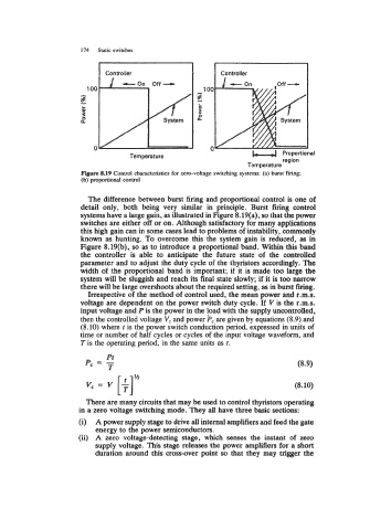
Figure 8.19 Control characteristics for zero-voltage switching systems: (a) burst f~ng;
(b) proportional control
The difference between burst firing and proportional control is one of
detail only, both being very similar in principle. Burst firing control
systems have a large gain, as illustrated in Figure 8.19(a), so that the power
switches are either off or on. Although satisfactory for many applications
this high gain can in some cases lead to problems of instability, commonly
known as hunting. To overcQme this the system gain is reduced, as in
Figure 8.19(b), so as to introduce a proportional band. Within this band
the controller is able to anticipate the future state of the controlled
parameter and to adjust the duty cycle of the thyristors accordingly. The
width of the proportional band is important; if it is made too large the
system will be sluggish and reach its final state slowly; if it is too narrow
there will be large overshoots about the required setting, as in burst firing.
Irrespective of the method of control used, the mean power and r.m.s.
voltage are dependent on the power switch duty cycle. If V is the r.m.s.
input voltage and P is the power in the load with the supply uncontrolled,
then the controlled voltage V, and power Pc are given by equations (8.9) and
(8.10) where t is the power switch conduction period, expressed in units of
time or number of half cycles or cycles of the input voltage waveform, and
T is the operating period, in the same units as f.
Pt
P, = - (8.9)
v, = v [4 (8.10)
T
M
There are many circuits that may be used to control thyristors operating
in a zero voltage switching mode. They all have three basic sections:
(i) A power supply stage to drive all internal amplifiers and feed the gate
energy to the power semiconductors.
(ii) A zero voltage-detecting stage, which senses the instant of zero
supply voltage. This stage releases the power amplifiers for a short
duration around this cross-over point so that they may trigger the