
Page 393 - Power Electronics Handbook
P. 393
382 Power semiconductor circuit applications
current, this occurring at the correct instant in the rotor position by virtue
of the commutator location, and the greater the number of commutator
segments, the smoother the torque produced.
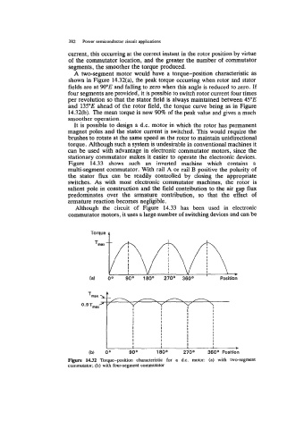
A two-segment motor would have a torque-position characteristic as
shown in Figure 14.32(a), the peak torque occurring when rotor and stator
fields are at WOE and falling to zero when this angle is reduced to zero. If
four segments are provided, it is possible to switch rotor current four times
per revolution so that the stator field is always maintained between 45"E
and 135"E ahead of the rotor field, the torque curve being as in Figure
14.32(b). The mean torque is now 90% of the peak value and gives a much
smoother operation.
It is possible to design a d.c. motor in which the rotor has permanent
magnet poles and the stator current is switched. This would require the
brushes to rotate at the same speed as the rotor to maintain unidirectional
torque. Although such a system is undesirable in conventional machines it
can be used with advantage in electronic commutator motors, since the
stationary commutator makes it easier to operate the electronic devices.
Figure 14.33 shows such an inverted machine which contains a
multi-segment commutator. With rail A or rail B positive the polarity of
the stator flux can be readily controlled by closing the appropriate
switches. As with most electronic commutator machines, the rotor is
salient pole in construction and the field contribution to the air gap flux
predominates over the armature contribution, so that the effect of
armature reaction becomes negligible.
Although the circuit of Figure 14.33 has been used in electronic
commutator motors, it uses a large number of switching devices and can be
Figure 1432 Torque-position characteristic for a d.c. motor: (a) with two-segment
commutator: (b) with four-segment commutator