
Page 395 - Power Electronics Handbook
P. 395
384 Power semiconductor circuit applications
Position
A X
B X
A' x
B' x
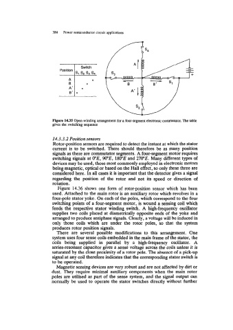
Figure 1435 Open-winding arrangement for a four-segment electronic commutator. The table
gives the switching sequence
14.3.3.2 Position sensors
Rotor-position sensors are required to detect the instant at which the stator
current is to be switched. There should therefore be as many position
signals as there are commutator segments. A four-segment motor requires
switching signals at VE, WE, 180"E and 270"E. Many different types of
devices may be used, those most commonly employed in electronic motors
being magnetic, optical or based on the Hall effect, so only these three are
considered here. In all cases it is important that the detector gives a signal
regarding the position of the rotor and not its speed or direction of
rota tion.
Figure 14.36 shows one form of rotor-position sensor which has been
used. Attached to the main rotor is an auxiliary rotor which revolves in a
four-pole stator yoke. On each of the poles, which correspond to the four
switching points of a four-segment motor, is wound a sensing coil which
feeds the respective stator winding switch. A high-frequency oscillator
supplies two coils placed at diametrically opposite ends of the yoke and
arranged to produce antiphase signals. Clearly, a voltage will be induced in
only those coils which are under the rotor poles, so that the system
produces rotor position signals.
There are several possible modifications to this arrangement. One
system uses four sense coils embedded in the main frame of the stator, the
coils being supplied in parallel by a high-frequency oscillator. A
series-resonant capacitor gives a sense voltage across the coils unless it is
saturated by the close proximity of a rotor pole. The absence of a pick-up
signal at any coil therefore indicates that the corresponding stator switch is
to be operated.
Magnetic sensing devices are very robust and are not affected by dirt or
dust. They require minimal auxiliary components when the main rotor
poles are utilised as part of the sense system, and the signal output can
normally be used to operate the stator switches directly without further