
Page 396 - Power Electronics Handbook
P. 396
Electrical machine control 385
structure
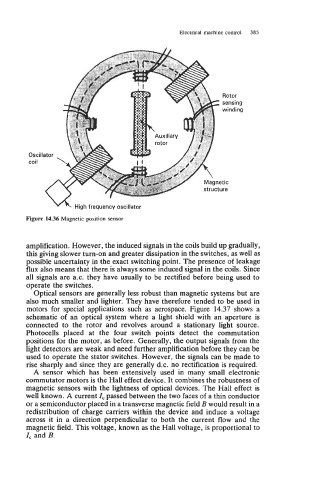
Figure 14.36 Magnetic position sensor
amplification. However, the induced signals in the coils build up gradually,
this giving slower turn-on and greater dissipation in the switches, as well as
possible uncertainty in the exact switching point. The presence of leakage
flux also means that there is always some induced signal in the coils. Since
all signals are a.c. they have usually to be rectified before being used to
operate the switches.
Optical sensors are generally less robust than magnetic systems but are
also much smaller and lighter. They have therefore tended to be used in
motors for special applications such as aerospace. Figure 14.37 shows a
schematic of an optical system where a light shield with an aperture is
connected to the rotor and revolves around a stationary light source.
Photocells placed at the four switch points detect the commutation
positions for the motor, as before. Generally, the output signals from the
light detectors are weak and need further amplification before they can be
used to operate the stator switches. However, the signals can be made to
rise sharply and since they are generally d.c. no rectification is required.
A sensor which has been extensively used in many small electronic
commutator motors is the Hall effect device. It combines the robustness of
magnetic sensors with the lightness of optical devices. The Hall effect is
well known. A current I, passed between the two faces of a thin conductor
or a semiconductor placed in a transverse magnetic field B would result in a
redistribution of charge carriers within the device and induce a voltage
across it in a direction perpendicular to both the current flow and the
magnetic field. This voltage, known as the Hall voltage, is proportional to
Z, and B.