
Page 394 - Power Electronics Handbook
P. 394
Electrical machine control 383
Rail A
I
I
Rail B
Figure 14.33 Inverted d.c. motor with multi-segment commutator
expensive. Figure 14.32(b) shows that, with a little sacrifice in torque
smoothness, a four-segment commutator can be used which would be
much more economical. Figures 14.34 and 14.35 illustrate two possible
winding arrangements for such a machine, and also show the switch-
operating periods. It is seen from these that although the open-winding
arrangement uses only half as many switches as the closed-winding
machine, its winding utilisation is only one quarter. Therefore it would
generally be physically larger and less efficient.
Figure 14.34 also shows that the switching action is very similar to that
obtained by a two-phase inverter where S4, S7, S3 and S8 constitute one
phase and Sz, S5, SI and S6 give the other. Thus essentially, as mentioned
earlier, there are two functions required to be performed by the
commutator in a d.c. machine. First, it must sense the relative position of
the stator and rotor fields, and second, it must switch the stator field
current at the appropriate instance. We will now examine these functions
in detail and see how they are performed by an electronic commutator.
Switch
Position
s, s, s, s, s, s, s, s,
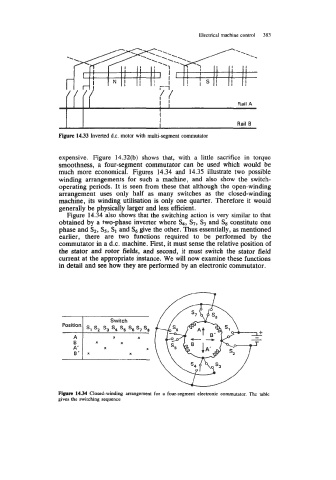
Figure 14.34 Closed-winding arrangement for a four-segment electronic commutator. The table
gives the switching sequence