
Page 114 - Power Quality in Electrical Systems
P. 114
Power Harmonic Filters 97
Current
Grid I s I a I LOAD harmonic
source
Z s
I pf
I af Z pf
Active Hybrid filter
filter Passive system
filters
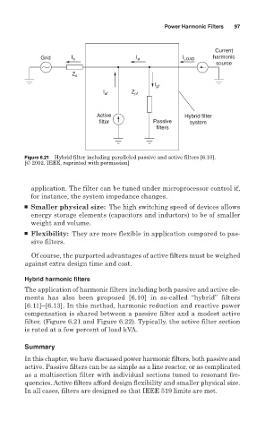
Figure 6.21 Hybrid filter including paralleled passive and active filters [6.10].
[© 2002, IEEE, reprinted with permission]
application. The filter can be tuned under microprocessor control if,
for instance, the system impedance changes.
■ Smaller physical size: The high switching speed of devices allows
energy storage elements (capacitors and inductors) to be of smaller
weight and volume.
■ Flexibility: They are more flexible in application compared to pas-
sive filters.
Of course, the purported advantages of active filters must be weighed
against extra design time and cost.
Hybrid harmonic filters
The application of harmonic filters including both passive and active ele-
ments has also been proposed [6.10] in so-called “hybrid” filters
[6.11]–[6.13]. In this method, harmonic reduction and reactive power
compensation is shared between a passive filter and a modest active
filter. (Figure 6.21 and Figure 6.22). Typically, the active filter section
is rated at a few percent of load kVA.
Summary
In this chapter, we have discussed power harmonic filters, both passive and
active. Passive filters can be as simple as a line reactor, or as complicated
as a multisection filter with individual sections tuned to resonant fre-
quencies. Active filters afford design flexibility and smaller physical size.
In all cases, filters are designed so that IEEE 519 limits are met.