
Page 109 - Power Quality in Electrical Systems
P. 109
92 Chapter Six
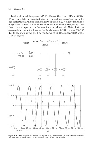
First, we’ll model the system in PSPICE using the circuit of Figure 6.18a.
We can calculate the expected total harmonic distortion of the load volt-
age using the calculated values shown in Table 6.2. We have found the
magnitude of the line impedance at each harmonic frequency, and
then the voltages at the harmonics are calculated. Note that the
expected rms output voltage at the fundamental is 277 8.4 268.6 V
due to the drop across the line reactance at 60 Hz. So, the THD of the
load voltage is
2
2
220.7 1 14.5 1 13.7 2
THD 5 5 10.7%
268.6
Ls R line Vo
220 uH 0.01
+
Vs − + + + +
l 1 − l 5 − l 7 − l 11 −
(a)
400 V
200 V
0 V
−200 V
−400 V
0 s 10 ms 20 ms 30 ms 40 ms 50 ms 60 ms 70 ms 80 ms 90 ms 100 ms
V(Vo) (b)
Figure 6.18 The original system of Example 6.3. (a) The circuit. (b) The PSPICE simula-
tion showing the load voltage. (c) The spectrum of the load voltage.