
Page 107 - Power Quality in Electrical Systems
P. 107
90 Chapter Six
this circuit, the short circuit current is
V s 277
I SC 5 5 5 7348 A
24
X s2dspds60ds10 d
L s
Therefore, the ratio I /I 7348/100 73.48. From Table 10.3 of
SC
L
IEEE-519, we see that the maximum current harmonic (for harmonics
less than the 11th) is 10 percent of the fundamental. Therefore, both the
5th and 7th harmonics violate this standard. We also violate the TDD
specification, which is
12 percent. In Figure 6.16b and Figure 6.16c, we
see the current waveform and spectrum, respectively.
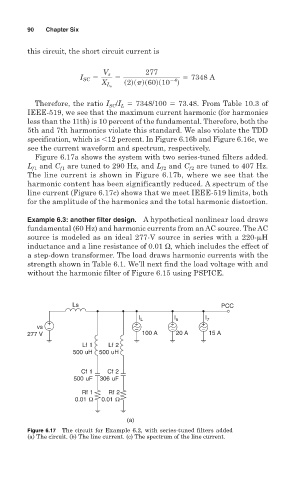
Figure 6.17a shows the system with two series-tuned filters added.
L and C are tuned to 290 Hz, and L and C are tuned to 407 Hz.
f1
f2
f2
f1
The line current is shown in Figure 6.17b, where we see that the
harmonic content has been significantly reduced. A spectrum of the
line current (Figure 6.17c) shows that we meet IEEE-519 limits, both
for the amplitude of the harmonics and the total harmonic distortion.
Example 6.3: another filter design. A hypothetical nonlinear load draws
fundamental (60 Hz) and harmonic currents from an AC source. The AC
source is modeled as an ideal 277-V source in series with a 220-
H
inductance and a line resistance of 0.01 Ω, which includes the effect of
a step-down transformer. The load draws harmonic currents with the
strength shown in Table 6.1. We’ll next find the load voltage with and
without the harmonic filter of Figure 6.15 using PSPICE.
Ls PCC
I L I 5 I 7
+ + + +
vs − − − −
277 V 100 A 20 A 15 A
Lf 1 Lf 2
500 uH 500 uH
Cf 1 Cf 2
500 uF 306 uF
Rf 1 Rf 2
0.01 Ω 0.01 Ω
(a)
Figure 6.17 The circuit for Example 6.2, with series-tuned filters added
(a) The circuit. (b) The line current. (c) The spectrum of the line current.