
Page 102 - Power Quality in Electrical Systems
P. 102
Power Harmonic Filters 85
impedance reduces to Z R. For other than resonance, the magnitude of
Z is given by:
2 2
2
2sRCvd 1 s1 2 LCv d
ZZZ 5
vC
1884
The impedance of a single-tuned section tuned to 300 Hz, or v r
rad/s, is shown in Figure 6.11b. Two values of R are shown, R 0.01 Ω
and 0.1 Ω, which becomes the impedance at resonance. The impedances
of the L and C at resonance are selected for the example as 0.94 Ω.
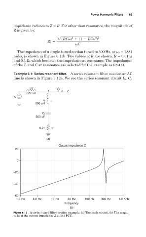
Example 6.1: Series resonant filter. A series resonant filter used on an AC
line is shown in Figure 6.12a. We see the series resonant circuit L , C ,
f
f
Ls Vo
Z
220 uH
+
v s −
L f L
500 uH
C f
563 uF
0.01 R
(a)
Output impedance Z
20
0
−20
−40
−60
1.0 Hz 3.0 Hz 10 Hz 30 Hz 100 Hz 300 Hz 1.0 KHz
Frequency
(b)
Figure 6.12 A series-tuned filter section example. (a) The basic circuit. (b) The magni-
tude of the output impedance Z at the PCC.