
Page 105 - Power Quality in Electrical Systems
P. 105
88 Chapter Six
Utility source Filter PCC
Rline Ls vpcc
0.01 220 uH I1
L1 L2 L3 + −
500 uH 500 uH 500 uH
C1 C2 C3
611 uF 312 uF 126 uF
R1 R2 R3
0.01 0.01 0.01
(a)
Impedance Z at the PCC
20
10
0
−10
−20
−30
−40
1.0 Hz 3.0 Hz 10 Hz 30 Hz 100 Hz 300 Hz 1.0 KHz
Frequency
(b)
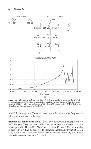
Figure 6.15 A harmonic multisection filter. This filter provides mimima at the 5th, 7th,
and 11th harmonics. The line is modeled as an ideal voltage source, with a line induc-
tance of 220 ΩH and a line resistance of 0.01 . (a) The circuit. (b) A PSPICE simula-
tion showing the impedance at the PCC.
mindful to design our filters so these peaks do not occur at frequencies
where harmonic currents exist.
Example 6.2: Series-tuned filters. Let’s now consider an example where
we’ll design a filter to attenuate harmonic currents drawn from the line
to comply with IEEE-519. Note the circuit of Figure 6.16a, where the
source is 277 V, line-to-neutral. The fundamental load current at 60 Hz
is I 100 A. This load also draws fifth-harmonic current I 20 A and
L
5
15 A.
seventh-harmonic current I 7