
Page 101 - Power Quality in Electrical Systems
P. 101
84 Chapter Six
Z
L
R
(a)
300 Hz trap
30
20
10
0
−10
−20
−30
−40
10 Hz 30 Hz 100 Hz 300 Hz 1.0 KHz
vdb(vo) Frequency
(b)
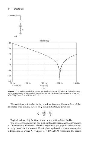
Figure 6.11 A series-tuned filter section. (a) The basic circuit. (b) A PSPICE simulation of
input impedance Z of a section tuned to the fifth-line harmonic (300Hz) with L 500
H,
C 563 µF, and R 0.01 Ω and 0.1 Ω.
The resistance R is due to the winding loss and the core loss of the
inductor. The quality factor, or Q of an inductor, is given by:
vL X L
Q 5 5
R R
Typical values of Q for filter inductors are 30 to 50 at 60 Hz.
The series resonant circuit has a dip in its series impedance at resonance
at the frequency where the inductive impedance and capacitive impedance
exactly cancel each other out. The single-tuned section is at resonance for
, where X X , or v 1/2LC . At resonance, the series
a frequency v r L C r