
Page 96 - Power Quality in Electrical Systems
P. 96
Power Harmonic Filters 79
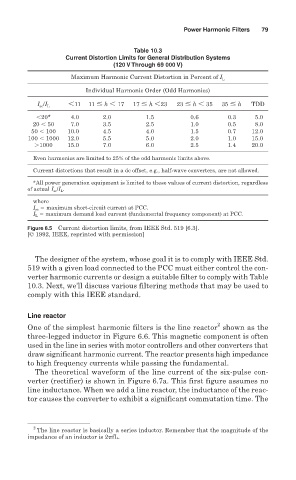
Table 10.3
Current Distortion Limits for General Distribution Systems
(120 V Through 69 000 V)
Maximum Harmonic Current Distortion in Percent of I L
Individual Harmonic Order (Odd Harmonics)
11 11 h
17 17 h
23 23 h
35 35 h TDD
I sc /I L
20* 4.0 2.0 1.5 0.6 0.3 5.0
20
50 7.0 3.5 2.5 1.0 0.5 8.0
50
100 10.0 4.5 4.0 1.5 0.7 12.0
100
1000 12.0 5.5 5.0 2.0 1.0 15.0
1000 15.0 7.0 6.0 2.5 1.4 20.0
Even harmonics are limited to 25% of the odd harmonic limits above.
Current distortions that result in a dc offset, e.g., half-wave converters, are not allowed.
*All power generation equipment is limited to these values of current distortion, regardless
of actual I sc /I L .
where
I sc maximum short-circuit current at PCC.
I L maximum demand load current (fundamental frequency component) at PCC.
Figure 6.5 Current distortion limits, from IEEE Std. 519 [6.3].
[© 1992, IEEE, reprinted with permission]
The designer of the system, whose goal it is to comply with IEEE Std.
519 with a given load connected to the PCC must either control the con-
verter harmonic currents or design a suitable filter to comply with Table
10.3. Next, we’ll discuss various filtering methods that may be used to
comply with this IEEE standard.
Line reactor
2
One of the simplest harmonic filters is the line reactor shown as the
three-legged inductor in Figure 6.6. This magnetic component is often
used in the line in series with motor controllers and other converters that
draw significant harmonic current. The reactor presents high impedance
to high frequency currents while passing the fundamental.
The theoretical waveform of the line current of the six-pulse con-
verter (rectifier) is shown in Figure 6.7a. This first figure assumes no
line inductance. When we add a line reactor, the inductance of the reac-
tor causes the converter to exhibit a significant commutation time. The
2
The line reactor is basically a series inductor. Remember that the magnitude of the
impedance of an inductor is 2 fL.