
Page 93 - Power Quality in Electrical Systems
P. 93
76 Chapter Six
Ideal System Harmonic source
source impedance LOAD
M
Filter
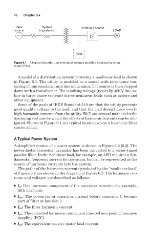
Figure 6.1 A typical distribution system showing a possible location for a har-
monic filter.
A model of a distribution system powering a nonlinear load is shown
in Figure 6.1. The utility is modeled as a source with impedance con-
sisting of line resistance and line inductance. The source is then stepped
down with a transformer. The resulting voltage (typically 480 V line-to-
line in three-phase systems) drives nonlinear loads such as motors and
other equipment.
Some of the goals of IEEE Standard 519 are that the utility presents
good quality voltage to the load, and that the load doesn’t draw overly
high harmonic currents from the utility. We’ll see several methods in the
upcoming sections by which the effects of harmonic currents can be mit-
igated. Shown in Figure 6.1 is a typical location where a harmonic filter
can be added.
A Typical Power System
A simplified version of a power system is shown in Figure 6.2 [6.2]. The
power-factor correction capacitor has been converted to a series-tuned
passive filter. In the nonlinear load, for example, an ASD requires a fun-
damental frequency current for operation, but can be represented as the
source of harmonic currents into the system.
The paths of the harmonic currents produced by the “nonlinear load”
of Figure 6.2 are shown in the diagram of Figure 6.3. The harmonic cur-
rents and voltages are described as follows:
■ I : One harmonic component of the converter current—for example,
h
fifth harmonic
■ I : The power-factor capacitor current before capacitor C became
hc
part of filter at location 3
■ I : The filter harmonic current
hf
■ I : The corrected harmonic component injected into point of common
hc
coupling (PCC)
■ I : The equivalent passive motor load current
hl