
Page 89 - Power Quality in Electrical Systems
P. 89
72 Chapter Five
by the lamp. The power factor correction circuit switches at a frequency
much higher than line frequency. Usually, the line side has passive filter-
ing to help reduce the high-frequency harmonics drawn from the AC line.
Transformers
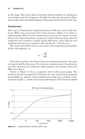
One source of harmonics using transformers with iron cores is the non-
linear B/H curve associated with these devices. Figure 5.11 shows a
representative B/H curve for electrical steel that may be used in a trans-
former core. Not shown here, purposely, is the hysteresis loop, since for
simplicity we’ll consider a single-valued B/H curve. Note that the core
material saturates at a magnetic flux density B ~ 2 Tesla or so.
The slope of the B/H curve at any point is the magnetic permeability
of the core material, or
dB
m 5
c
dH
From this equation, note that as the core material saturates, the mag-
netic permeability decreases. For economic reasons, power transformers
are often operated at a relatively high magnetic flux density, above the
B/H curve “knee.”
Shown in Figure 5.12a is a magnetic circuit without an airgap. The
magnetic circuit is comprised of N turns, the core material has magnetic
permeability m , and the cross-sectional area of the core is A with a char-
c
acteristic length, l , which is the mean path length of the flux lines inside
c
B/H curve for electrical steel
2.5
2
B, Tesla 1.5
1
0.5
0
1 10 100 1000 10000 100000
H, A-turns/m
Figure 5.11 A representative nonlinear B/H curve.