
Page 87 - Power Quality in Electrical Systems
P. 87
70 Chapter Five
+
i a
a
b I L V L
c
−
(a)
i (t)
a
I L
ω
90° 180° 270° 360°
−I L
(b)
Spectrum for ideal three-phase bridge
1.20
1.00
0.80
Amplitude 0.60
0.40
0.20
0.00
1 2 3 4 5 6 7 8 9 10 11 12 13 14
Harmonic number (N)
(c)
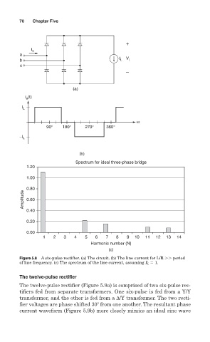
Figure 5.8 A six-pulse rectifier. (a) The circuit. (b) The line current for L/R period
of line frequency. (c) The spectrum of the line current, assuming I L 1.
The twelve-pulse rectifier
The twelve-pulse rectifier (Figure 5.9a) is comprised of two six-pulse rec-
tifiers fed from separate transformers. One six-pulse is fed from a Y/Y
transformer, and the other is fed from a ∆/Y transformer. The two recti-
fier voltages are phase shifted 30 from one another. The resultant phase
current waveform (Figure 5.9b) more closely mimics an ideal sine wave