
Page 90 - Power Quality in Electrical Systems
P. 90
Harmonic Current Sources 73
Mean path length l c
i(t) N Permeability µ c
v(t)
Area A c
(a)
v(t)
i(t)
t
(b)
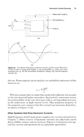
Figure 5.12 An inductor that draws nonlinear current. (a) The circuit. The induc-
tor has N turns; a mean path length, l c ; core permeability, m c ; and a core cross-
sectional area, A c . (b) The waveforms of inductor voltage, v(t), and the inductor
current, i(t).
the core. From magnetic circuit analysis, we can find the inductance of this
structure as:
AN 2
m c
L 5
l c
We’ll now assume that we excite this circuit with sufficient volt-seconds
so the core material begins saturation. Equivalently, saturation means
the permeability of the core decreases with a corresponding decrease
in the inductance at high current levels. This nonlinear property of
the magnetic core requires that the current has harmonic distortion,
as shown in Figure 5.12b.
Other Systems that Draw Harmonic Currents
High-frequency switch-mode power supplies are covered extensively in
Chapter 7. Other sources of harmonic currents are adjustable speed
drives (ASDs), motors, and arc furnaces. Figure 5.13 illustrates the typ-
ical line current and spectrum for an adjustable speed drive.