
Page 98 - Power Quality in Electrical Systems
P. 98
Power Harmonic Filters 81
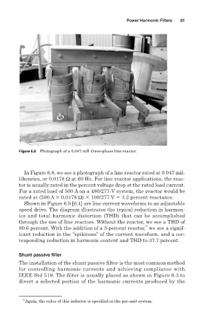
Figure 6.8 Photograph of a 0.047 mH three-phase line reactor.
In Figure 6.8, we see a photograph of a line reactor rated at 0.047 mil-
lihenries, or 0.0178 Ω at 60 Hz. For line reactor applications, the reac-
tor is usually rated in the percent voltage drop at the rated load current.
For a rated load of 500 A on a 480/277-V system, the reactor would be
rated at (500 A 0.0178 Ω) 100/277 V 3.2 percent reactance.
Shown in Figure 6.9 [6.4] are line current waveforms to an adjustable
speed drive. The diagram illustrates the typical reduction in harmon-
ics and total harmonic distortion (THD) that can be accomplished
through the use of line reactors. Without the reactor, we see a THD of
3
80.6 percent. With the addition of a 3-percent reactor, we see a signif-
icant reduction in the “spikiness” of the current waveform, and a cor-
responding reduction in harmonic content and THD to 37.7 percent.
Shunt passive filter
The installation of the shunt passive filter is the most common method
for controlling harmonic currents and achieving compliance with
IEEE Std 519. The filter is usually placed as shown in Figure 6.3 to
divert a selected portion of the harmonic currents produced by the
3
Again, the value of this inductor is specified in the per-unit system.