
Page 103 - Power Quality in Electrical Systems
P. 103
86 Chapter Six
480-V bus
(a)
3.50 500 kVAr tuned cap bank
Magnification of harmonic current from ASDS 2.50 No capacitor bank
3.00
2.00
1.50
1.00
0.50
0.0
1 3 5 7 9 11 13 15 17 19 21 23 25
Harmonic number
(b)
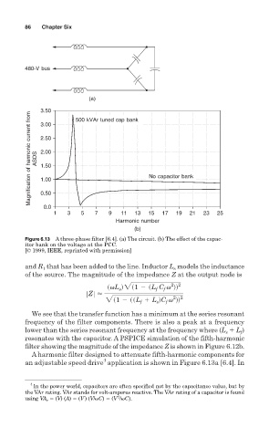
Figure 6.13 A three-phase filter [6.4]. (a) The circuit. (b) The effect of the capac-
itor bank on the voltage at the PCC.
[© 1999, IEEE, reprinted with permission]
and R that has been added to the line. Inductor L models the inductance
s
1
of the source. The magnitude of the impedance Z at the output node is
2 2
svL d2s1 2 sL C v dd
f
s
f
ZZZ<
2 2
2s1 2 ssL 1 L dC v dd
f
s
f
We see that the transfer function has a minimum at the series resonant
frequency of the filter components. There is also a peak at a frequency
lower than the series resonant frequency at the frequency where (L L )
f
s
resonates with the capacitor. A PSPICE simulation of the fifth-harmonic
filter showing the magnitude of the impedance Z is shown in Figure 6.12b.
A harmonic filter designed to attenuate fifth-harmonic components for
4
an adjustable speed drive application is shown in Figure 6.13a [6.4]. In
4
In the power world, capacitors are often specified not by the capacitance value, but by
the VAr rating. VAr stands for volt-amperes reactive. The VAr rating of a capacitor is found
2
using VA r (V) (A) (V ) (V/ C) (V / C).