
Page 121 - Power Quality in Electrical Systems
P. 121
104 Chapter Seven
V CC
L
+
i (t)
D sw C R L V O
–
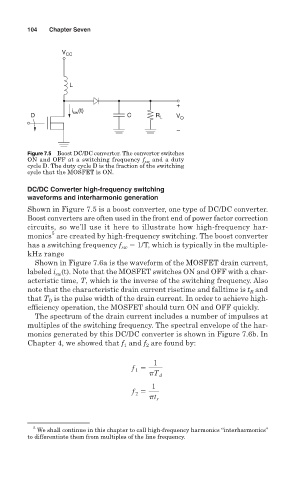
Figure 7.5 Boost DC/DC converter. The converter switches
ON and OFF at a switching frequency f sw and a duty
cycle D. The duty cycle D is the fraction of the switching
cycle that the MOSFET is ON.
DC/DC Converter high-frequency switching
waveforms and interharmonic generation
Shown in Figure 7.5 is a boost converter, one type of DC/DC converter.
Boost converters are often used in the front end of power factor correction
circuits, so we’ll use it here to illustrate how high-frequency har-
5
monics are created by high-frequency switching. The boost converter
has a switching frequency f sw 1/T, which is typically in the multiple-
kHz range
Shown in Figure 7.6a is the waveform of the MOSFET drain current,
labeled i (t). Note that the MOSFET switches ON and OFF with a char-
sw
acteristic time, T, which is the inverse of the switching frequency. Also
and
note that the characteristic drain current risetime and falltime is t R
that T is the pulse width of the drain current. In order to achieve high-
D
efficiency operation, the MOSFET should turn ON and OFF quickly.
The spectrum of the drain current includes a number of impulses at
multiples of the switching frequency. The spectral envelope of the har-
monics generated by this DC/DC converter is shown in Figure 7.6b. In
Chapter 4, we showed that f and f are found by:
2
1
1
f
1
pT d
1
f
2
pt r
5
We shall continue in this chapter to call high-frequency harmonics “interharmonics”
to differentiate them from multiples of the line frequency.