
Page 124 - Power Quality in Electrical Systems
P. 124
Switch Mode Power Supplies 107
To utility
50 µH
0.1 µF
1 µF To
R term D.U.T
50 Ω
To spectrum analyzer
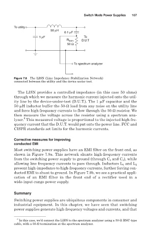
Figure 7.8 The LISN (Line Impedance Stabilization Network)
connected between the utility and the device under test.
The LISN provides a controlled impedance (in this case 50 ohms)
through which we measure the harmonic current injected onto the util-
ity line by the device-under-test (D.U.T.). The 1
F capacitor and the
50
H inductor buffer the 50- load from any noise on the utility line
and force high frequency currents to flow through the 50- resistor. We
then measure the voltage across the resistor using a spectrum ana-
6
lyzer. This measured voltage is proportional to the injected high fre-
quency current that the D.U.T. would put onto the power line. FCC and
CISPR standards set limits for the harmonic currents.
Corrective measures for improving
conducted EMI
Most switching power supplies have an EMI filter on the front end, as
shown in Figure 7.9a. This network shunts high-frequency currents
from the switching power supply to ground (through C and C ), while
3
2
allowing line frequency currents to pass through. Inductors L and L 2
1
present high-impedance to high-frequency currents, further forcing con-
ducted EMI to shunt to ground. In Figure 7.9b, we see a practical appli-
cation of an EMI filter in the front end of a rectifier used in a
wide-input-range power supply.
Summary
Switching power supplies are ubiquitous components in consumer and
industrial equipment. In this chapter, we have seen that switching
power supplies generate high-frequency voltages and currents, and that
6
In this case, we’d connect the LISN to the spectrum analyzer using a 50- BNC-type
cable, with a 50- termination at the spectrum analyzer.