
Page 65 - Power Quality in Electrical Systems
P. 65
48 Chapter Four
+
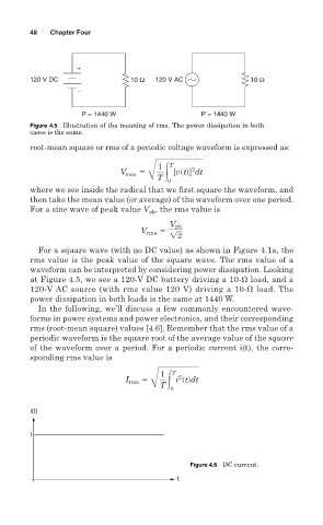
120 V DC 10 Ω 120 V AC 10 Ω
−
P = 1440 W P = 1440 W
Figure 4.5 Illustration of the meaning of rms. The power dissipation in both
cases is the same.
root-mean square or rms of a periodic voltage waveform is expressed as:
1 T 2
V rms 5 3 [vstd] dt
Å T
0
where we see inside the radical that we first square the waveform, and
then take the mean value (or average) of the waveform over one period.
, the rms value is
For a sine wave of peak value V pk
V pk
V rms 5 !2
For a square wave (with no DC value) as shown in Figure 4.1a, the
rms value is the peak value of the square wave. The rms value of a
waveform can be interpreted by considering power dissipation. Looking
at Figure 4.5, we see a 120-V DC battery driving a 10- load, and a
120-V AC source (with rms value 120 V) driving a 10- load. The
power dissipation in both loads is the same at 1440 W.
In the following, we’ll discuss a few commonly encountered wave-
forms in power systems and power electronics, and their corresponding
rms (root-mean square) values [4.6]. Remember that the rms value of a
periodic waveform is the square root of the average value of the square
of the waveform over a period. For a periodic current i(t), the corre-
sponding rms value is
1 T
2
I rms 5 3 i stddt
Å T
0
i(t)
I
Figure 4.6 DC current.
t