
Page 234 - Practical Design Ships and Floating Structures
P. 234
209
Figure 5 : The Vertical Displacement RAO( 1, / L = 0.2, Incident Angle=O degree)
1
0.9 -
os - -D snt(h-sa.sm)
'-1 5B 5.6 5.4 51 0 0.2 0.4 0.6 OB 1
N~ndlmmdc.nd L.n@
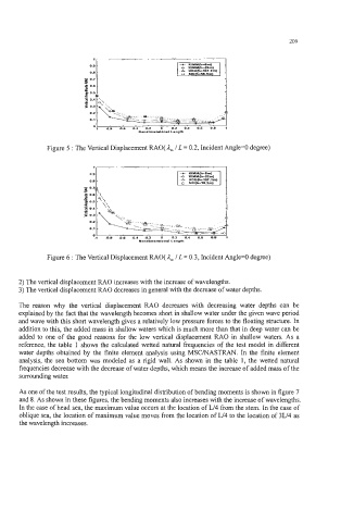
Figure 6 : The Vertical Displacement RAO( 1- L = 0.3, Incident Angle=O degree)
/
2) The vertical displacement RAO increases with the increase of wavelengths.
3) The vertical displacement RAO decreases in general with the decrease of water depths.
The reason why the vertical displacement RAO decreases with decreasing water depths can be
explained by the fact that the wavelength becomes short in shallow water under the given wave period
and wave with this short wavelength gives a relatively low pressure forces to the floating structure. In
addition to this, the added mass in shallow waters which is much more than that in deep water can be
added to one of the good reasons for the low vertical displacement RAO in shallow waters. As a
reference, the table 1 shows the calculated wetted natural frequencies of the test model in different
water depths obtained by the finite element analysis using MSCMASTRAN. In the finite element
analysis, the sea bottom was modeled as a rigid wall. As shown in the table 1, the wetted natural
frequencies decrease with the decrease of water depths, which means the increase of added mass of the
surrounding water.
As one of the test results, the typical longitudinal distribution of bending moments is shown in figure 7
and 8. As shown in these figures, the bending moments also increases with the increase of wavelengths.
In the case of head sea, the maximum value occurs at the location of L/4 from the stem. In the case of
oblique sea, the location of maximum value moves from the location of L/4 to the location of 3L/4 as
the wavelength increases.