
Page 233 - Practical Design Ships and Floating Structures
P. 233
208
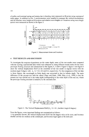
of pulley and torsional spring and strains due to bending were measured at 40 points using waterproof
strain gages. In addition to this, 3 accelerometers were installed to measure the vertical accelerations
and the absolute wave heights at 8 locations and relative wave heights at 4 locations using wave height
meters were measured as shown in the figure 3.
Figure 3 : Measurement items and locations
4 TEST RESULTS AND DISCUSSION
To investigate the response-dependence on the water depth, some of the test results were compared
with the existing experimental data which were obtained by using different model scales for the same
prototype floating structure and summarized in the figures 4, 5 and 6. Figure 4, figure 5 and figure 6
show the vertical displacement RAO at the centerline of the test model in regular waves with the
incident angle 0 degree with A, / L = 0.1,0.2 and 0.3, respectively. For the comparison of the test data
in these figures, the wavelength in finite depth was converted to that in infinite depth. The main
difference of the present test with the others (Yago and Endo, 1996; Shin, et al., 1999) is that the
present test was carried out in the water depth corresponding to the water depth of the real sea, where
the prototype floating structure is installed, by the similarity law.
Figure 4 : The Vertical Displacement RAO( A, / L = 0.1, Incident Angle=O degree)
From the figures, some important findings are summarized as follows:
1) As generally known, the vertical displacement RAO has the largest value at the stem, and becomes
smaller and has the smallest at the central part, and becomes lager again at the stem part.