
Page 228 - Practical Design Ships and Floating Structures
P. 228
203
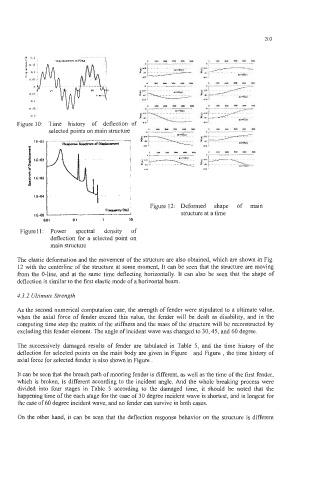
Figure IO: Time history of deflection of
selected points on main structure
Figure 12: Deformed shape of main
FmnNww;
1€05 structure at a time
(Lo1 01 1 10
Figurell: Power spectral density of
deflection for a selected point on
main structure
The elastic deformation and the movement of the structure are also obtained, which are shown in Fig.
12 with the centerline of the structure at some moment, It can be seen that the structure are moving
from the 0-line, and at the same time deflecting horizontally. It can also be seen that the shape of
deflection is similar to the first elastic mode of a horizontal beam.
4.3.2 Ultimate Strength
As the second numerical computation case, the strength of fender were stipulated to a ultimate value,
when the axial force of fender exceed this value, the fender will be dealt as disability, and in the
computing time step the matrix of the stiffness and the mass of the structure will be reconstructed by
excluding this fender element. The angle of incident wave was changed to 30,45, and 60 degree.
The successively damaged results of fender are tabulated in Table 5, and the time history of the
deflection for selected points on the main body are given in Figure and Figure , the time history of
axial force for selected fender is also shown in Figure .
It can be seen that the breach path of mooring fender is different, as well as the time of the first fender,
which is broken, is different according to the incident angle. And the whole breaking process were
divided into four stages in Table 5 according to the damaged time, it should be noted that the
happening time of the each stage for the case of 30 degree incident wave is shortest, and is longest for
the case of 60 degree incident wave, and no fender can survive in both cases.
On the other hand, it can be seen that the deflection response behavior on the structure is different