
Page 226 - Practical Design Ships and Floating Structures
P. 226
20 1
TABLE 3
COMPARISON OF EIGEN ANGULAR FREQUENCY
OF VLFS BY ANALYTICAL METHOD AND FEM
3.
0. 0.25 0.5 a75 LO
WkW~
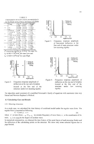
Figure 3: Frequency response amplitude
of horizontal deflection at the
free end of main structure under
low mooring rigidity
b=6.963 X 10⁴N/m2,for case Low and
L=3.920X 10⁴N/m2 for case High
. 2.
0. 0.25 0.5
Angul:&.(d$
Figure 4: Frequency response amplitude of
Figure 2: Frequency response amplitude of deflection at the top end of dolphin
deflection at the top end of dolphin located at the free end of the
located at the free end of the structure under low mooring
structure under low mooring rigidity rigidity
The algorithm used consisted of a modified Newmark's family of equations with automatic time step
feature and Newton-Raphson's Method.
4.3 Calculating Case and Results
4.3. I Mooring clearance
As a study case, we calculated the time history of combined model under the regular wave force. The
regular force is assumed as following.
F, = F, sin( k-x, - o I) (8)
where F is wave force, (=2z )is circular frequency of wave force, x , is the coordinates of the
node, (=k/cos(a))is the degree of incident wave.
In numerical computation, we obtained the time history of the axial forces of each mooring fender and
the deflection of the calculating points on the structure. We show only some selected figures due to
page limited.