
Page 304 - Practical Design Ships and Floating Structures
P. 304
279
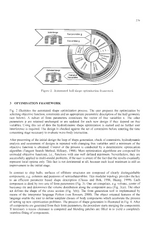
Figure 2. Automated hull shape optimisation framework
3 OPTIMISATION FRAMEWORK
Fig. 2 illustrates the automated shape optimization process. The user prepares the optimization by
selecting objective function, constraints and an appropriate parametric description of the hull geometry
(see below). A subset of form parameters constitutes the vector of free variables x. The other
parameters p are retained unchanged or are updated for each new design if they depend on free
variables. Using this set of data the hydrodynamic shape optimization is started and no further user
interference is required. The design is checked against the set of constraints before entering the time
consuming stage necessary to evaluate wave-body interaction.
After processing of the initial design the loop of shape generation, check of constraints, hydrodynamic
analysis and assessment of designs is repeated with changing free variables until a minimum of the
objective function is obtained. Control of the process is conducted by a deterministic optimization
algorithm (Tangent Search Method; Hilleary, 1966). Most optimization algorithms are composed for
unimodal objective functions, Le., functions with one well defined minimum. Nevertheless, they are
successfully applied to multi-modal problems, if the user is aware of the fact that the results eventually
represent local optima only. This fact is not detrimental at all, because each local minimum is still an
improvement to the initial stage.
In contrast to ship hulls, surfaces of offshore structures are composed of clearly distinguishable
components, e.g. columns and pontoons of semisubmersibles. This modular topology provides the key
to an efficient parameter based shape description (Clauss and Birk, 1996; Huang, 1999). Each
component is deed by two sets of form parameters (Fig. 3). One set comprises, e.g. volume, center of
buoyancy etc and determines the volume distribution along the component axis (Fig. 3(a)). The other
set defines the shape of the cross section (Fig. 3(b)). The form generation tool is implemented by
means of the interpreter language Python (van Rossum, 2000). The object oriented features of the
language enable the user to define template classes of body components which accelerate the process
of setting up new optimization problems. The process of shape generation is illustrated in Fig. 4. After
all components are generated from their form parameters, the procedure starts merging the components.
If necessary a recess clearance is computed and blending patches are filled in to yield a completely
seamless fitting of components.