
Page 305 - Practical Design Ships and Floating Structures
P. 305
280
.---
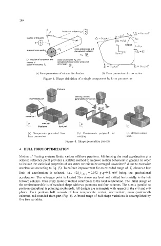
location of first point
s section area and
shape of cross sectio erivative at end point
5 = direction of Component axis cmm section area A+, and < J
volume V derivative of cross section area curve .----
center of buoyancy 5, at first point d5 Ip B = (XC3,YC3)' --a
e = (Xc4;Yc4)4)r
(a) Form parameters of volume distribution (h) Form parameters of cross section
Figure 3. Shape definition of a single component by form parameters
blending patches
(a) Components generated from (h) Components prepared for (c) Merged compe
form parameters merging nents
Figure 4. Shape generation process
4 HULL FORM OPTIMIZATION
Motion of floating systems limits various offshore perations. Minimizing the total acceleration at a
selected reference point provides a suitable method to improve motion behaviour in general. In order
to include the statistical properties of sea states we minimize averaged downtime P d due to excessive
acceleration according to Eq. (5). To enforce improvement for an extended range of To -classes a low
limit of acceleration is selected, i.e., (2i,),,,,,",, = 0.072. g ,g=9.81m/s2 being the gravitational
acceleration. The reference point is located 25m above sea level and shifted horizontally to the left
forward column. Thus every mode of motion contributes to the total acceleration. The initial design of
the semisubmersible is of standard shape with two pontoons and four columns. The x-axis (parallel to
pontoon centreline) is pointing southwards. All designs are symmetric with respect to the x=O and y=O
planes. Each pontoon half consists of four components: central, intermediate, main (underneath
column), and rounded front part (Fig. 4). A broad range of hull shape variations is accomplished by
five free variables: