
Page 396 - Practical Design Ships and Floating Structures
P. 396
37 I
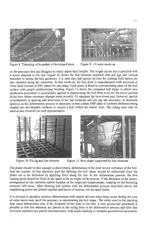
Figure 8: Trimming of boundary of developed piece Figure 9: 1/3 scale mock-up
on the precision bed and designed to easily adjust their lengths. The length can be fine controlled with
a screw attached at the end. Figure 10 shows the line elements installed with pin jigs and vertical
members to define the hull geometry. It is seen also that special devices for jointing both halves are
also installed along the centerline. In this mock-up, the hull plate is manufactured with plywood of
3mm thick instead of FRF' plates for real ships. Each piece is fitted to corresponding parts of the hull
surface with simple unidirectional bending. Figure 11 shows the competed hull shape in which new
production procedure is successfully applied in representing the hull form even for the lower portion
of the bow where curvature changes most severely. To represent the bow-lower part, however, special
consideration in spacing and directions of the line elements and pin jigs are necessary. A structural
analysis on the deformation process is necessary in that a plane FRP plate of uniform thickness being
shaped into developable surfaces to consist a hull within the elastic limit. The ruling lines may be
used as line elements for hull representation.
Figure 10: Pin jig and line element Figure 11: Bow shape supported by line elements
The plates should be thin enough to allow elastic deformation of the most severe curvature of the hull.
And the number of line elements used for defining the hull shape should be minimized since the
plates are to be deformed by applying force along the line. In the deformation process, the first
loading point should be fixed in the space to be an origin of the process. If the thickness of the plates,
arrangement in line elements andor location of the origin are inappropriate, warping on the bounding
contours will occur. After forming hull surface with the deformation process described above, the
neighboring plates are jointed together and layers of laminas will be stack inside.
It is advised to carefully monitor deformations with optical devices since those occur during the cure
of extra layers may spoil the accuracy in representing the hull shape. The roller used in the stacking
may cause deformation also if the thickness of the plate is too thin. A new production procedure is
possible in that line elements are placed on the ruling lines in the deformation process and after that
structural members are placed simultaneously with inside stacking to maintain geometrical accuracies.