
Page 394 - Practical Design Ships and Floating Structures
P. 394
369
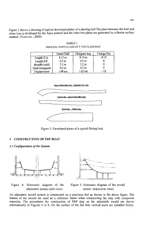
Figure 3 shows a drawing of typical developed plates of a planing hull.The plate between the keel and
chine line is developed by the Apex method and the other two plates are generated by a Bezier surface
method. (Yoon etc., 2000)
TABLE 1
PRINCIPAL PARTICULARS OF 3 TON CLASS BOAT
Length 0.A 8.15111 8.14m
Length B.P. 6.5 m 6.5 m
Breadth (mld) 2.2 m 2.2 m
M (designed) 0.2 m 0.2 m
Di lacement 1.68 ton 1.65 ton -1.8
Figure 3: Developed plates of a typical fishing boat
3 CONSTRUCTION OF FRP BOAT
3.1 Configuration of the System
Figure 4: Schematic diagram of the Figure 5: Schematic diagram of the mould
adjustable system (side view) system (transverse view)
An adjustable mould system is constructed on a precision bed as shown in the above figure. The
frames of the mould are used as a reference frame when constructing the ship with composite
materials. The procedures for construction of FRP ship on the adjustable mould are shown
schematically in Figures 4 to 6. On the surface of the flat bed, vertical posts are installed firmly.