
Page 395 - Practical Design Ships and Floating Structures
P. 395
370
Vertical and horizontal pin jigs as well as metal rings for wire connections are attached on the surface
of the mould and the vertical posts, respectively. Developable hull surfaces can be represented by the
line elements. Battens made of circular pipes are attached along the line elements and their exact
shapes and locations are maintained by wires and pin jigs. The plates are link together to complete the
hull shape and additional laminas are stacked inside until necessary thickness is obtained. The battens
are aligned with the line elements and their shapes are maintained by the pulling of the wire and the
pushing from the pin jig.
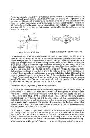
Figure 6: Top view of hull form Figure 7: Joining method of developed plate
The Velcro attached on the hull surface prevents damages from wires and pin jigs. Number of the
battens for definition of hull shape should be minimized to improve the productivity. Inner parts may
help deforming the plate but is not recommended because bonding and stacking of extra layers inside
is necessary in the procedure. The thickness of the plate should be determined carefully since the plate
should be thin enough to deform hull shape easily in the elastic range but thick enough not to have
excessive distortion during inner stacking and curing process. Stacking process is carried out inside of
the developed pieces laid on the flat bed. To allow a scarp joint between the neighboring plates
stacking should be planned to have thicker layer at the center and thinner on the boundaries. The
developed pieces are bended in the elastic range to represent the hull shape and neighboring plates are
assembled with mechanical devices as shown in Figure 7. The strength of the assembled plates shown
in Figure 7 is not enough and so additional inner stacking process is necessary to guarantee adequate
strength of the bonded plate. Box keels, strakes, spray strips and etc. are attached on the hull surface
by the secondary bonding to complete the construction of the FRP boat.
3.2 Mock-up Test for Verification of the Construction Method
A 1/3 and a full scale models are constructed to verify the proposed method and to identify the
possible flaws of the method. The hull surface is divided into several pieces and developed into a
plane surface. Stacking processes for each piece should proceed cautiously not to cross over the
bounding curves since each piece will be trimmed along the curves before the resin being completely
cured and Figure 8 shows the procedure. Since the whole process of stacking laminas can be done on
the flat bed, efficiencies go up with improvement in working condition, resin consumption downs and
uniform quality can be maintained. The trimming of boundaries of the developed pieces before
complete curing will improve environmental condition of ship yards by reducing dust production and
since the scraps may be pressed to have less volume.
The 113 scale pieces shown in Figure 8 can be deformed within the elastic limit to form a developable
hull perfectly as shown in Figure 9. At the fore body portion front of the 6th station, hull shape varies
rapidly and a full scale mock-up is need to be constructed for evaluation of the construction
techniques more carellly. However, construction of the fore body is the most difficult part of the
process and hence a production precision bed is manufactured with I-beams to have uniform spacing
of 500mm and a total working space of 4,000 mmx 4,000 mm. The pin jigs made of pipe are installed