
Page 494 - Practical Design Ships and Floating Structures
P. 494
469
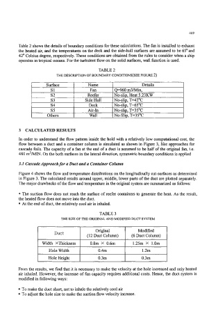
Table 2 shows the details of boundary conditions for these calculations. The fan is installed to exhaust
the heated air, and the temperatures on the deck and the side-hull surfaces are assumed to be 65' and
42' Celsius degree, respectively. These conditions are obtained from the rules to consider when a ship
operates in tropical oceans. For the turbulent flow on the solid surfaces, wall function is used.
TABLE 2
THE DESCRIPTION OF BOUNDARY CONDITIONS(SEE FIGURE 2)
Surface Name Details
s1 Fan Q+60 m3Min,
s2 Reefer No-slip, Heat 5.23KW
s3 Side Hull No-slip, T=42OC
s4 Deck No-slip, T=65OC
s5 Air-In No-slip, T=35'C
Others Wall No-Slip, T=35'C
3 CALCULATEDRESULTS
In order to understand the flow pattern inside the hold with a relatively low computational cost, the
flow between a duct and a container column is simulated as shown in Figure. 3, like approaches for
cascade foils. The capacity of a fan at the end of a duct is assumed to be half of the original fan, i.e.
480 m3NlN. On the both surfaces in the lateral direction, symmetric boundary conditions is applied
3.1 Cascade Approach for a Duct and u Contabter Column
Figure 4 shows the flow and temperature distributions on the longitudinally cut-surfaces as determined
in Figure 3. The calculated results around upper, middle, lower parts of the duct are plotted separately.
The major drawbacks of the flow and temperature in the original system are summarized as follows:
The suction flow does not reach the surface of reefer containers to generate the heat. As the result,
the heated flow does not move into the duct.
At the end of duct, the relatively cool air is inhaled.
TABLE 3
THE SIZE OF THE ORIGINAL AND MODIFIED DUCT SYSTEM
Duct Origid Modified
(1 2 Duct Column) (6 Duct Column)
I Width XThickness 1 0.8m X 0.6m I 1.25m X 1.Om I
Hole Width 0.4m 1.2m
Hole Height 0.3m 0.3m
From the results, we find that it is necessary to make the velocity at the hole increased and only heated
air inhaled. However, the increase of fan capacity requires additional costs. Hence, the duct system is
modified in following ways:
To make the duct short, not to inhale the relatively cool air
To adjust the hole size to make the suction flow velocity increase.