
Page 65 - Practical Design Ships and Floating Structures
P. 65
40
and the formation of the barges should be improved to reduce the resistance of the fleet.
The mooring force was measured when navigating on the route of NANTONG-PAOTAIWAN. When
the test was carried out, the wind speed reached up 6-7 Beaufort scale. The maximum force was
31.2kN while rudder angle was 0 degree and 147.96kN while the angle was 25 degree, 274.4kN
breaking force of mooring steel hawser was enough for the fleet under the test condition.
4 RENOVATION OF EXISTING INTEGRATED BARGE
Considering shipowner’s assign condition and the restricting of the CHANGJIANG route, two kinds of
3000t and 5000t integrated barges are selected as investigation targets. As two kinds of barge were
originally designed to navigate on the river route, the strength are unsuitable for the sea route. In order
to navigate on the route of BEILUN to PAOTAIWAN(be1onging to the shelter sea area), the shell and
bottom structure of the 5000t barge must be replaced, that is too expensive for shipowner. For the
3000t barge, a few modifications such as reducing the cargo hatch opening and structural strengthening
can make it suitable for the sea route. So the 3000t integrated barge was selected at last to renovate.
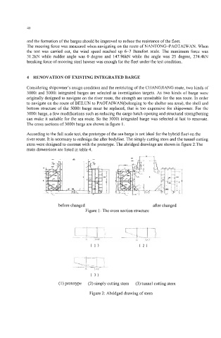
The cross sections of 3000t barge are shown in figure 1.
According to the full scale test, the prototype of the sea barge is not ideal for the hybrid fleet on the
river route. It is necessary to redesign the after bodyline. The simply cutting stern and the tunnel cutting
stem were designed to contrast with the prototype. The abridged drawings are shown in figure 2.The
main dimensions are listed in table 4.
*
before changed der changed
Figure 1 : The cross section structure
(3)
(1) prototype (2) simply cutting stem (3) tunnel cutting stern
Figure 2: Abridged drawing of stem