
Page 118 - Practical Machinery Management for Process Plants Major Process Equipment Maintenance and Repair
P. 118
Installation, Maintenance, and Repair of Krtical Pumps 103
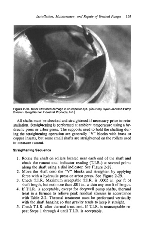
Figure 2-30. Minor cavitation damage in an impeller eye. (Courtesy Byron Jackson Pump
Division, Borg-Warner Industrial Products, Inc.)
All shafts must be checked and straightened if necessary prior to rein-
stallation. Straightening is performed at ambient temperature using a hy-
draulic press or arbor press. The supports used to hold the shafting dur-
ing the straightening operation are generally “V” blocks with brass or
copper inserts, but some small shafts are straightened on the rollers used
to measure runout.
Straightening Sequence
1. Rotate the shaft on rollers located near each end of the shaft and
check the runout total indicator reading (T.I.R.) at several points
along the shaft using a dial indicator. See Figure 2-28.
2. Move the shaft onto the “V” blocks and straighten by applying
force with a hydraulic press or arbor press. See Figure 2-29.
3. Check T.I.R. Maximum acceptable T.I.R. is .0005 in. per ft of
shaft length, but not more than BO1 in. within any one ft of length.
4. If T.I.R. is acceptable, except for deepwell pump shafts, thermal
treat in a furnace to relieve peak residual stresses in accordance
with Table 2-2. Thermal treatment must be performed vertically
with the shaft hanging so that gravity tends to keep it straight.
5. Check T.I.R. after thermal treatment. If T.I.R. is unacceptable re-
peat Steps 1 through 4 until T.I.R. is acceptable.