
Page 113 - Practical Machinery Management for Process Plants Major Process Equipment Maintenance and Repair
P. 113
98 Major Process Equipment Maintenance and Repair
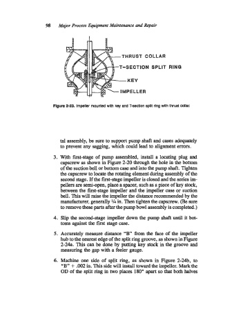
THRUST COLLAR
T-SECTION SPLIT RING
Figure 2-23. Impeller mounted with key and T-section split ring with thrust collar.
tal assembly, be sure to support pump shaft and cases adequately
to prevent any sagging, which could lead to alignment errors.
3. With first-stage of pump assembled, install a locating plug and
capscrew as shown in Figure 2-20 through the hole in the bottom
of the suction bell or bottom case and into the pump shaft. Tighten
the capscrew to locate the rotating element during assembly of the
second stage. If the first-stage impeller is closed and the series im-
pellers are semi-open, place a spacer, such as a piece of key stock,
between the first-stage impeller and the impeller case or suction
bell. This will raise the impeller the distance recommended by the
manufacturer, generally 1/4 in. Then tighten the capscrew. (Be sure
to remove these parts after the pump bowl assembly is completed.)
4. Slip the second-stage impeller down the pump shaft until it bot-
toms against the first stage case.
5. Accurately measure distance “B” from the face of the impeller
hub to the nearest edge of the split ring groove, as shown in Figure
2-24a. This can be done by putting key stock in the groove and
measuring the gap with a feeler gauge.
6. Machine one side of split ring, as shown in Figure 2-24b, to
+
“By’ .002 in. This side will install toward the impeller. Mark the
OD of the split ring in two places 180” apart so that both halves