
Page 111 - Practical Machinery Management for Process Plants Major Process Equipment Maintenance and Repair
P. 111
96 Major Process Equipment Maintenance and Repair
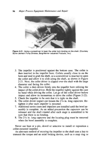
Figure 2-21. Using a screwdriver to keep the collet from binding on the shaft. (Courtesy
Byron Jackson Pump Division, Borg-Warner Industrial Products, Inc.)
3. The impeller is positioned against the bottom case. The collet is
then inserted in the impeller bore. Collets usually close in on the
bore and tend to grab the shaft, so a screwdriver is inserted to open
the collet and allow it to slide along the shaft, as shown in Figure
2-21. Next, the collet driver is slipped over the shaft with the large
diameter end facing the collet.
4. The collet is then driven firmly into the impeller bore utilizing the
impact of the collet driver. Hold the impeller tightly against the case
by hand while driving the collet. Let go of the collet driver before
impact and allow its momentum to drive the collet (Figure 2-22).
5. Check the impeller to be sure that it is tight on the shaft.
6. The collet driver impact can loosen the 2% in. long capscrew. Re-
tighten it after each impeller is mounted.
7. Additional series cases and impellers are installed until the bowl as-
sembly is complete. As an added precaution the capscrew can be
released and the shaft rotated after each stage is assembled to be
sure that there is no binding.
8. The 2% in. long capscrew and the locating plug must be removed
when the bowl assembly is complete.
Never use heat or a pin, dowel or setscrew to install or reposition a
collet-mounted impeller.
An alternate method of securing the impeller to the shaft uses a key to
transmit the torque and an axial locking device, such as a snap ring or