
Page 114 - Practical Machinery Management for Process Plants Major Process Equipment Maintenance and Repair
P. 114
Installation, Maintenance, and Repair of Ertical Pumps 99
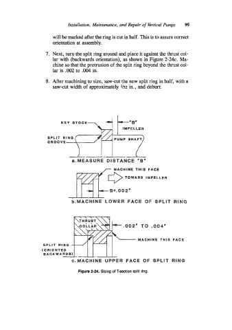
will be marked after the ring is cut in half. This is to assure correct
orientation at assembly.
7. Next, turn the split ring around and place it against the thrust col-
lar with (backwards orientation), as shown in Figure 2-24c. Ma-
chine so that the protrusion of the split ring beyond the thrust col-
lar is .002 to .004 in.
8. After machining to size, saw-cut the new split ring in half, with a
saw-cut width of approximately 1/32 in., and deburr.
KEY STOCK
SPLIT RING
GROOVE
rg?02e
a.MEASURE DISTANCE 'B'
MACHINE THIS FACE
TOWARD IMPELLER
b.MACHINE LOWER FACE OF SPLIT RING
\\\ \
k.002' TO .004'
MACHINE THIS FACE
/
SPLIT RING
(ORIENTED
BACK WARDS)
c.MACHlNE UPPER FACE OF SPLIT RING
Flgure 2-24. Sizing of T-section split ring.