
Page 161 - Practical Machinery Management for Process Plants Major Process Equipment Maintenance and Repair
P. 161
Positive Displacement and Dynamic Blowers 143
4. Remove nondrive end cover (7).
5. Remove flathead socket cap screw (29, 69), rotor shaft washer
(25), and oil slinger (21) from nondrive end of each rotor.
6. Remove timing gears (8):
7. Place the blower on its side as shown in Figure 4-2A.
8. Remove the gear lock nuts (35) from shafts.
9. Rotate the gears to the position shown in Figure 4-2A-keyways in
line and gear timing arrows matched. Mark gears with reference
marks-five teeth below timing marks.
10. Turn the gears upward five teeth so the reference marks are
matched as shown in Figure 4-2B. This gear position is necessary
when pulling one gear first so rotors will clear and not jam.
11. Pull the driven gear first, using a gear puller. It is assembled in
two parts-gear rim and hub. Do not disassemble. Do not inter-
change the dowel pins (58); they are select fitted.
12. Remove the drive gear. Keep the key (24) together with the gear.
13. Remove end plates (4 & 5):
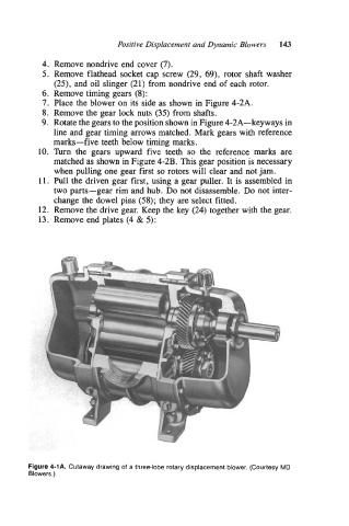
Figure 4-1A. Cutaway drawing of a three-lobe rotary displacement blower. (Courtesy MD
Blowers.)