
Page 156 - Practical Machinery Management for Process Plants Major Process Equipment Maintenance and Repair
P. 156
138 Major Process Equipment Maintenance ond Repair
cess conditions will allow), or using pump parts made of materials resis-
tant to cavitation damage, such as high-chrome steels.
Maintenance of liquid ring machines is minimized because there are no
wearing parts other than bearings and seals. The bulk of necessary main-
tenance efforts should be aimed at the service water, seal fluid, and pres-
sure regulating systems. This necessitates careful monitoring by operat-
ing personnel. In addition to these it is necessary to monitor bearing
health by vibration analysis, shock pulse, or spike energy methods.
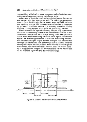
When disassembly for repairs is necessary there are very important de-
tails to ensure that running clearances are reestablished correctly. In ma-
chines with cone type inlet and discharge porting, axial rotor position is
critical, especially where running clearances are on tapered surfaces as in
Figure 3-13. You can appreciate that an axial shift will close up the clear-
ance on one end and open it up on the other. In Figure 3-13 the thrust end
bearing is on the left hand side. Shimming is used at this end under the
bearing cap to adjust the axial position. When machines of this design are
disassembled, note the shim thickness removed. If the entire rotor assem-
bly is being replaced, compare the distance marked "A" on the new and
the old rotor and adjust the shim thickness accordingly.
t-*1 t--7
Figure 513. Clearance checks required for vacuum pump rotors.