
Page 48 - Practical Machinery Management for Process Plants Major Process Equipment Maintenance and Repair
P. 48
Installation, Maintenance, and Repair of Horizontal Pumps 33
- 1w
140
6 130- 90
D
U 120 BO
- 120-
c
f 110- 110 70 'f
0 n
2100- c 1w 60%
i 7
90 'g 90 50 a.
U
9 : 40 .I
c
F 80- e4 ..
a YI
70- 70 30
80 Ni
50 10
40 0
Capacity -% of design
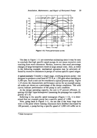
Figure 1-12. Pump performance curves.
The data in Figure 1-1 1 are somewhat misleading since it may be easy
to conclude that high specific speed pumps do not cause excessive costs
resulting from worn clearances. Beware, however, that small percentage
changes of large horsepowers result in large annual costs. Also, as noted
in the following example, mechanical operation may be adversely af-
fected by excessive clearances in pumps of various specific speed ranges.
A typical example: Consider a single stage, overhung process pump-one
designed to produce a total head of 725 ft at 1,550 gpm when operating at
3,550 rpm. Such a unit can be considered a typical process pump. Figure
1-12 shows the characteristic performance curves for an example pump;
all scales are shown as a percentage of the design conditions. The solid
curves indicate performance of the pump in new condition.
At the design operating capacity, the unit is 67 percent efficient, re-
quiring 424 bhp* input horsepower (assuming the pumpage has a specific
gravity of 1 .O).
Referring to the specific speed nomogram (Figure 1-13), it is deter-
mined that our example pump has a specific speed of 1,OOO.
Now, going back to Figure 1-1 1, we see that if the wear rings have
worn to the point where running clearances have doubled (increased by
100 percent), a pump having a specific speed of 1,OOO will suffer an in-
* Brake horsepower