
Page 93 - Practical Machinery Management for Process Plants Major Process Equipment Maintenance and Repair
P. 93
78 Major Process Equipment Maintenance and Repair
ADJUSTINQ NUT- \
PUMP HEAD SHAFT
LOCKINQ ARM
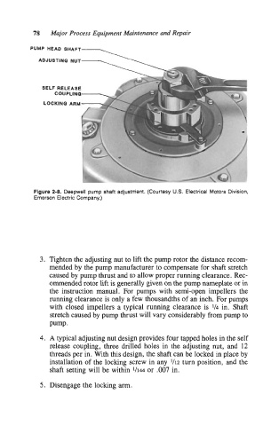
Figure 2-8. Deepwell pump shaft adjustment. (Courtesy US. Electrical Motors Division,
Emerson Electric Company.)
3. Tighten the adjusting nut to lift the pump rotor the distance recom-
mended by the pump manufacturer to compensate for shaft stretch
caused by pump thrust and to allow proper running clearance. Rec-
ommended rotor lift is generally given on the pump nameplate or in
the instruction manual. For pumps with semi-open impellers the
running clearance is only a few thousandths of an inch. For pumps
with closed impellers a typical running clearance is 1/4 in. Shaft
stretch caused by pump thrust will vary considerably from pump to
Pump.
4. A typical adjusting nut design provides four tapped holes in the self
release coupling, three drilled holes in the adjusting nut, and 12
threads per in. With this design, the shaft can be locked in place by
installation of the locking screw in any 1/12 turn position, and the
shaft setting will be within 1/14 or .007 in.
5. Disengage the locking arm.