
Page 132 - Practical Power System and Protective Relays Commissioning
P. 132
Voltage Transformers Chapter | 11 131
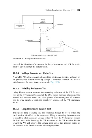
FIGURE 11.10 Voltage transformer ratio test.
checked for direction of movement in the galvanometer and if it is in the
positive direction then the polarity is ok.
11.7.4 Voltage Transformer Ratio Test
A variable AC voltage source advanced test set is used to inject voltages on
the primary side and the secondary voltage is measured to check that the VT
ratio is correct for each phase, as shown in Fig. 11.10.
11.7.5 Winding Resistance Test
Using this test we can measure the secondary resistance of the VT for each
core at the VT terminal box and at the LCC panels between phases and the
neutral, and between phases and other phases, after opening the VT connec-
tion to relay panels or metering panels by opening all the VT secondary
MCBs.
11.7.6 Loop Resistance Burden Test
This test is done to ensure that the connected burden to VT is within the
rated burden, identified on the nameplate. Using a secondary injection tester
to inject the rated secondary voltage of the VT from the VT terminals toward
the load side while isolating the VT terminals at the VT terminal blocks
toward the VT and observe the voltage drop across the injection points as
the burden can be found from the following equation: