
Page 127 - Practical Power System and Protective Relays Commissioning
P. 127
126 Practical Power System and Protective Relays Commissioning
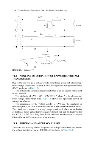
FIGURE 11.4 Inductive VT.
11.3 PRINCIPLE OF OPERATION OF CAPACITIVE VOLTAGE
TRANSFORMERS
Due to the cost we use a voltage divide capacitance along with electromag-
netic voltage transformer to form in total the capacitive voltage transformer
(CVT) as shown in Fig. 11.5.
This reduces the insulation requirements then later; as a result of this cost
is also reduced.
The total ratio of CVT 5 ððC1 1 C2Þ=C1Þ 3 T where T is the electromag-
netic voltage transformer ratio. Fig. 11.6 shows the equivalent circuit of
voltage transformer.
The capacitance of the voltage divider in CVT and the reactance in
electromagnetic VT form a resonance circuit called a Ferroresonance circuit.
This circuit when subjected to a step change in voltage leads to an oscillation
of nonlinear nature called Ferroresonance which in turn can be dangerous for
the VT if it is left for a long time. Earth switch is therefore used to absorb
this oscillation in Ferroresonance relay scheme.
11.4 BURDENS AND ACCURACY CLASSES
There are two accuracy classes for protective voltage transformer and meter-
ing voltage transformer as per IEC 60044-2 as shown in Table 11.1.