
Page 125 - Practical Power System and Protective Relays Commissioning
P. 125
124 Practical Power System and Protective Relays Commissioning
where K n is the rated ratio and V p and V s are the primary and secondary
terminal voltages. If the error is positive, the secondary voltage exceeds the
rated value. The phase error is the phase difference between the secondary
and the primary voltage phasors. It is positive when the secondary voltage
leads the primary voltage phasor. According to the ratio and angle error, all
VTs are required to comply with one of the classes as defined in IEC60044-
2, measuring the VT accuracy class (0.1, 0.2, 0.5, 1, and 3) or protective VT
accuracy class (3P or 6P).
VTs should be of a sufficient size as to prevent measured disturbances
from inducing saturation in the VT. For transients, this generally requires
that the knee point of the VT saturation curve be at least 200% of the rated
system voltage. It is always good practice to incorporate some allowance in
the calculations for overvoltage conditions. The frequency response of stan-
dard metering and protection class VTs depend on their type and burden.
In general, the burden should be very high impedance. This is generally
not a problem with most monitoring equipment available today. Power
quality monitoring instruments, intelligent electronic devices (IEDs), and
other instruments all present very high impedance to the VT. With a high
impedance burden, the response is usually adequate to at least 5 kHz. While
working in energized V.T it is very dangerous to short circuit the secondary
winding of the voltage transformer.
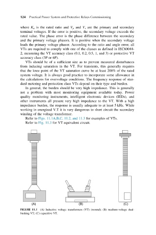
Refer to Figs. 11.1A,B,C, 11.2, and 11.3 for examples of VTs.
Refer to Fig. 11.3 for VT equivalent circuit.
FIGURE 11.1 (A) Inductive voltage transformers (VT) (wound); (B) medium-voltage dual-
bushing VT; (C) capacitive VT.