
Page 126 - Practical Power System and Protective Relays Commissioning
P. 126
Voltage Transformers Chapter | 11 125
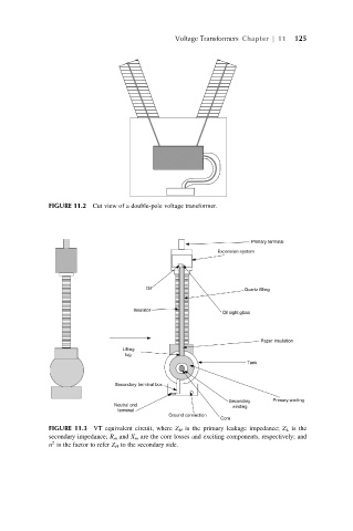
FIGURE 11.2 Cut view of a double-pole voltage transformer.
FIGURE 11.3 VT equivalent circuit, where Z H is the primary leakage impedance; Z L is the
secondary impedance; R m and X m are the core losses and exciting components, respectively; and
2
n is the factor to refer Z H to the secondary side.