
Page 121 - Practical Power System and Protective Relays Commissioning
P. 121
Traditional and Electronic Current Transformers Theory Testing Chapter | 10 119
10.9.2.2 Winding Resistance Test
During this test we can measure the secondary resistance of the CT for each
core after opening the CT connection to relay panels or metering panels.
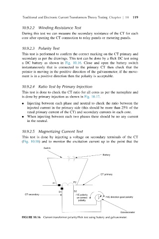
10.9.2.3 Polarity Test
This test is performed to confirm the correct marking on the CT primary and
secondary as per the drawings. This test can be done by a flick DC test using
a DC battery as shown in Fig. 10.16. Close and open the battery switch
instantaneously that is connected to the primary CT then check that the
pointer is moving in the positive direction of the galvanometer; if the move-
ment is in a positive direction then the polarity is acceptable.
10.9.2.4 Ratio Test by Primary Injection
This test is done to check the CT ratio for all cores as per the nameplate and
is done by primary injection as shown in Fig. 10.17.
Injecting between each phase and neutral to check the ratio between the
injected current in the primary side (this should be more than 25% of the
rated primary current of the CT) and secondary currents in each core.
When injecting between each two phases there should be no any current
in the neutral.
10.9.2.5 Magnetizing Current Test
This test is done by injecting a voltage on secondary terminals of the CT
(Fig. 10.18) and to monitor the excitation current up to the point that the
FIGURE 10.16 Current transformer polarity/flick test using battery and galvanometer.