
Page 122 - Practical Power System and Protective Relays Commissioning
P. 122
120 Practical Power System and Protective Relays Commissioning
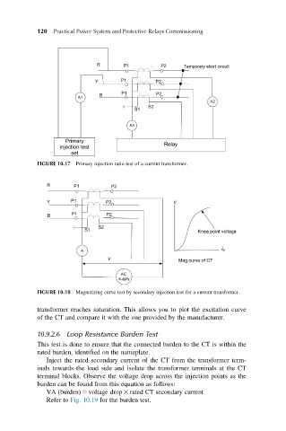
FIGURE 10.17 Primary injection ratio test of a current transformer.
FIGURE 10.18 Magnetizing curve test by secondary injection test for a current transformer.
transformer reaches saturation. This allows you to plot the excitation curve
of the CT and compare it with the one provided by the manufacturer.
10.9.2.6 Loop Resistance Burden Test
This test is done to ensure that the connected burden to the CT is within the
rated burden, identified on the nameplate.
Inject the rated secondary current of the CT from the transformer term-
inals towards the load side and isolate the transformer terminals at the CT
terminal blocks. Observe the voltage drop across the injection points as the
burden can be found from this equation as follows:
VA (burden) 5 voltage drop 3 rated CT secondary current
Refer to Fig. 10.19 for the burden test.